
HYDROSTATIC TESTING

HYDROSTATIC TESTING
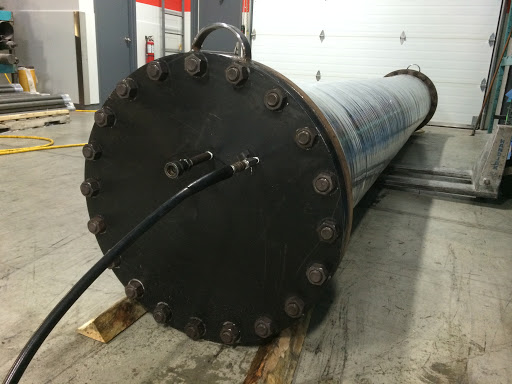
Hydrostatic testing by pressurizing vessels such as pipelines and gas cylinders, to both verify integrity and detect leaks. These tests involve filling the vessel or pipeline system with a liquid, usually water, which may be dyed to aid in visual leak detection. The vessel is then pressurized to a specific test pressure and monitored for any pressure loss. The location of a leak can be visually identified more easily if the test liquid contains a colorant. Overall vessel integrity is typically determined by measuring permanent deformation of the container.
Hydrostatic testing is the most common method employed for testing pipes and pressure vessels. These tests help maintain safety standards and ensure the integrity of a vessel or pipeline system over time. Testing of pressure vessels for transport and storage of gases is very important because such containers can explode if they fail under pressure.
Pipelines need to perform reliably and consistently — even in the harshest environments. At times, pressure can reach extreme levels. As one of the most trusted hydrostatic testing companies, we ensure your piping and systems are up to the task.
Effective and Efficient hydrostatic testing services are:
- Cost-effective and money-saving
- Highly efficient and time-saving
- Reliable, giving you peace of mind
- A perfect complement to our industrial system cleaning solutions
We provide extensive experience and can develop value-added plans during critical path commissioning to remove any confusion, so your team can stay focused on construction and commissioning.
Hydrostatic Testing Basics
Hydrostatic testing is a procedure designed to test for strength and leaks in piping systems, boilers, gas cylinders and pressure vessels to confirm they’ll operate properly, even under extreme conditions. Tests are typically required after repairs and shutdowns to validate equipment can successfully return to operation. Testing is conducted at higher pressures than normal operating pressures, typically up to 150 percent of the designed pressure.
Preparation and requirements prior to hydrotesting
1.A pretest check shall be made to ensure that pipe/support “contact” has been achieved at all support locations. This includes temporary supports provided only for the purpose of hydrotest.
2.The temporary supports should be designed (specially for large bore heavy piping) to ensure they are able to sustain the hydrostatic loads. This verification may not be critical for small bore piping systems. Removal of temporary support should be done only after the test is complete and the lines are fully drained.
3.All lines shall be checked to ensure the entire system can be completely drained after testing.
4.Vents or other high point connections shall be opened to displace air from lines once the water filling starts during the hydrostatic test.
5.All joints including structural attachments shall be left uninsulated/primed and exposed during hydrostatic testing. Some company procedures may allow exceptions to this requirement subject to certain conditions being met such as extended test durations and use of highly qualified welders.
1.All equipment which is to be excluded from the test shall be either disconnected from the system or positively isolated using spectacle blinds or blind flanges.
2.Expansion joints and spring supports shall be provided with temporary restraints or stops to prevent excessive travel or deformation under the hydrostatic test loads.
3.In-line valves should be in full open position during the hydrostatic leak test. Some companies recommend that ball valves should be in a partial open position as this allows the valve body cavity to be subjected to the pressure test.
4.Orifice plates, spray nozzles and similar restrictions should normally be installed after completion of tests.
5.When dismantling of piping is necessary to perform testing, less expensive gaskets suitable for the test pressure may be substituted. After completion of the test, the test gaskets shall be replaced by the gaskets required as per piping specifications.
6.Prefabricated spacers and spool pieces shall be fabricated and supplied to the correct test pressure rating by the contractor for replacing in-line instrumentation during plant testing and flushing, except for equipment such as control valves, with butt welding ends (which will be installed initially without internals and provided with a blind flange). Special attention shall be given to the provision of spacers and spool pieces required for equipment packages.

Hydrostatic Testing Process
We understand there is no one-size fits all hydrostatic pressure test. We plan, design and implement testing procedures to ensure the integrity of your unique equipment and piping. We serve industrial companies across a range of industries, such as chemical production and oil & gas businesses with a process that’s complete, proven and designed to save you time and money. We provide detailed plans in which we inspect your equipment, determine the proper testing approach and then deliver documentation and proof of testing results.
Hydrotest Fluid
The default hydrotest fluid in most cases is water. Water used for hydrostatic testing of piping shall be fresh, clean and free from suspended solids and other foreign matter. Water may not be used as a hydrostatic test medium under the following circumstances:
- the presence of water in the piping system may have adverse effects during plant start-up and operation.
- the piping material or its lining may deteriorate in the presence of hydrotest fluid.
- there is a likelihood of test water to be contaminated during testing and its disposal may pose environmental hazards.
- drop in ambient temperature may cause water to freeze during the test.
If the test fluid temperature produces condensation on the piping exterior surface, the water shall be heated to a temperature above the dew point or the test shall be delayed until such time that condensation will not occur on the external surface of the piping system under test. Water used for testing of stainless steel pipework shall not contain more than 30ppm chlorides. Some owners permit up to 50pmm chlorides and some owners impose a maximum limit of 15ppm chlorides. This caution is exercised to avoid pitting and stress corrosion cracking in 300-series stainless steels.
Water used for testing may be treated with chemical additives such as oxygen scavenger, biocide and corrosion inhibitor a good reason to use water for pressure testing is explained here . Hence, disposal of test fluid shall be carried out in accordance with the local environmental regulations.
Flushing
Prior to the hydrotest, the system shall be flushed with the dedicated test medium to remove all dirt and foreign matter. Recommended methods of flushing are:
- for lines up to 6” diameter, liquid volume flushing. For this method the minimum velocity in the largest pipe diameter to be not less than 3 meters/second.
- for lines over 6” diameter, hydroblast by means of self climbing high pressure water jet nozzles (Dynorod method) or approved equivalent.
- for air, halon and hydraulic lines, air blast cleaning ensuring a minimum velocity of 10 meters/second at the outlet end is achieved.
All necessary precautions shall be taken to avoid debris being pushed into associated equipment or “dead ends”.
Flushing shall proceed in an intermittent manner allowing time between flushes for debris to be cleared from line. Flushing shall continue for sufficient time to ensure that line is cleaned to the satisfaction of the Company.
Pressure Test Manifold
A pressure test manifold is used for performing a hydrotest. The pressure test manifold has the required provisions to test and protect the piping system subject to hydrotest and comprises of the following:
- Manifold provided with end caps suitable for the system pressure testing. It is recommended that all joints in a test manifold are of welded type and should be subject to 100% non-destructive examination by MPI and Radiography.
- Pressure relief valve of adequate capacity to relieve the system of any overpressure.
- A manual bleed valve for emergency bleeding and depressurisation of the piping system, should the relief valve fail.
- A pressure gauge, pressure recorder and temperature recorder connection. The pressure gauge should be calibrated preferably within 4 weeks of the test being carried out. The hydrotest pressure should preferably fall within 35-75% of the full range of pressure gauge.
- A connection to connect the hydrotest or pneumatic pump to the manifold.
- A connection to connect the test manifold to the low point of the piping system for filling and pressurisation.
- Hoses that connect the pumps to the test manifold and the test manifold to the piping system shall be rated for the test pressure and fitted with safety chains of sufficient strength that will prevent whipping of the hose, should the coupling get disconnected.
- All valves and fittings on the manifold shall be of the next higher rating.
- The strength of the test manifold should be validated by testing the manifold between 1.2 to 1.4 times of its rated system test pressure. Note that ASME B31.3 code does not provide any guidance on the recommended test pressure. These are based on construction industry practices.

Requirements during pressure test
During the pressure test, the pressure shall be gradually increased to allow time for material to equalize the strains. After the piping subject attains the required test pressure, it is recommended to stay clear from the test area for a period of 10 minutes before examining the joints and connections for leaks. As per para. 345.2.2 of ASME B31.3, a hydrostatic leak test shall be maintained for at least 10 minutes and all joints and connections shall be examined for leaks. Many company specifications prescribe a minimum hold time of 30 minutes to detect small seepage leaks and to permit a thorough inspection of joints and connections.
For internally coated piping such as FBE coated piping system, it should be ensured that coating is not damaged when subject to the full test pressure.
When the test has to be maintained for a period of time during which thermal expansion of the test medium might occur due to changes in ambient temperature, the contractor should ensure that the test system is not subjected to a pressure greater than the specified test pressure.
A flanged joint at which a spectacle blind or blank is inserted to isolate other equipment during the test need not be examined for leaks. These joints should be subject to a flange management procedure and leak tested during initial service.
Requirements after pressure test
All piping should be completely drained of all test fluid. Special attention may be required to ensure draining of pockets where the test fluid is likely to be trapped. While draining the system, due care should be exercised to open one of the vent valves to ensure that the piping system is not subject to vacuum and subsequent collapse. All piping tested with water, in which the presence of water is detrimental to the process start-up and operation should be thoroughly dried. The piping shall be blown-down with air to ensure that there are no trapped water pockets and the piping is dry.
Sensitive Leak Test
Where the Owner considers both hydrostatic and pneumatic leak testing impracticable, the alternative specified in para. 345.9 of ASME B31.3 which requires the system to be subjected to a Sensitive Leak Test may be used if both of the following conditions apply:
- a hydrostatic test would damage linings or internal insulation, or contaminate a process which would be hazardous, corrosive, or inoperative in the presence of moisture, or would present the danger of brittle fracture due to low metal temperature during the test
- a pneumatic test would present an undue hazard of possible release of energy stored in the system, or would present the danger of brittle fracture due to low metal temperature during the test
Piping required to have a sensitive leak test as per line list will be tested by the Gas and Bubble Formation Testing Method specified in Article 10, Section V of the ASME Boiler Pressure Vessel Code. Sensitivity of the test shall not be less than 10-3 atm-ml/sec (100 Pa-ml/s) under test conditions.
The test pressure shall be at least the lesser of 1.00 bar (100 kPa) gage, or 25% of the design pressure.
The pressure shall be gradually increased until a gauge pressure the lesser of one-half the test pressure or 1.70 bar (170 kPa) is attained, at which time a preliminary check shall be made. Then the pressure shall be gradually increased in steps until the test pressure is reached, the pressure being held long enough at each step to equalize piping strains.
If a Sensitive Leak test is required, joints will also be left unprimed and unpainted.
Waiver of Hydrostatic Test
Waiver of hydrostatic test in most organisations requires approval of the owners integrity assurance department. A waiver of hydrotest may be given due consideration by the integrity department if it can be proven that the contractor has exhausted all possible options available to perform testing of the piping system.

For more information, procurements and services contact GZ Industrial Supplies.
Readers also like
Understanding Pressure Testing Methods: A Comprehensive Guide to Pipe Pressure Testing and Leak Detection
Newest Guide & Blog Updates
")
Drill Machine Price in Nigeria (Types & Best Brands)
Introduction Drill machines are among the most essential power tools used across Nigeria’s construct...
 updated")
Top Industrial Cleaning Chemicals in Nigeria (2026) updated
Introduction In Nigeria’s thriving industrial sector, maintaining clean, safe, and high-performing w...

Industrial Cleaning Safety Standards: Best Practices, PPE & Compliance Guide for Nigerian Industries
Introduction Industrial cleaning environments are among the most hazardous workplaces due to exposur...
")
POWER TOOL NAMES AND USES (Complete List for Construction, Workshop & DIY 2026)
Introduction Power tools are essential equipment used in construction, fabrication, woodworking, and...
")
The Best Water Pumps in Nigeria (2026 Reviews & Price Guide)
Introduction Water is essential for homes, farms, and industries in Nigeria but access to reliable w...
")
How to Reduce Welding Defects with the Right Gas and Electrodes (2026 Guide)
Introduction Welding is a critical process in industries such as construction, fabrication, oil & ga...